
|
 04-20-2011
|
#121 |
|
Join Date: Apr 2009
Location: Prather, CA
Posts: 809
|
(I tried to post this update yesterday at the same time I posted on the "other" forum, but couldn't get this forum to load)
Time to get this beast timed! I used Marc Haibeck's LT5 timing article and also Dynomite's write up on timing his LT5 (links to both below for reference). http://www.zr1specialist.com/HAT%20W..._camshafts.htm http://www.zr1.net/forum/showthread....7524&post87524 Before moving on to the timing process, I installed the 2 new ARP rod bolts I ordered from Haibeck for that one piston I had to remove. I weighed both the ARP bolts and the original bolts and they are all the same (1.3oz IIRC), so the balance of the rotating mass won't be compromised. I used the GM torquing procedure since I don't have one of those fancy bolt stretch gauges. Marc lists the GM procedure as an "alternate" procedure for torquing the ARP rod bolts. 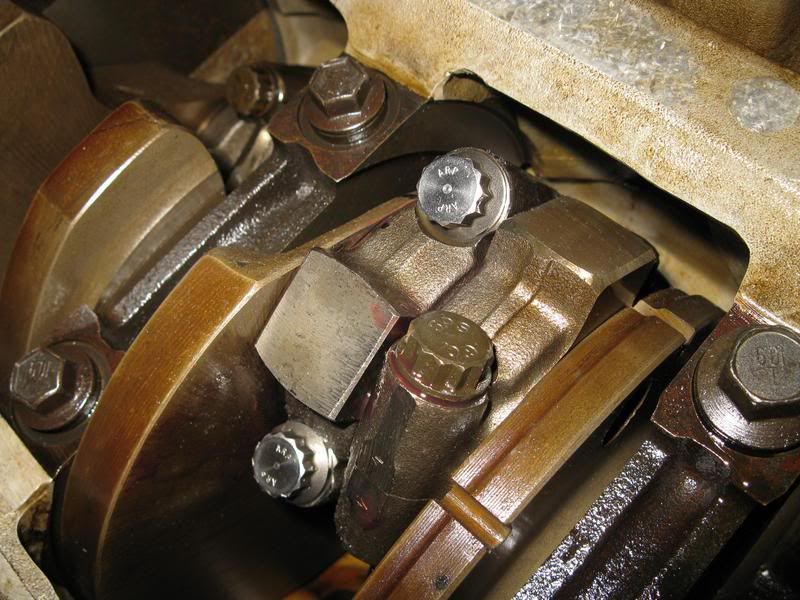 Now on to the timing. First I mounted my timing wheel to the front of the crank snout. I made a pointer out of a metal hanger and bolted it to one of the front cover holes. 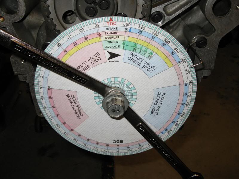 I installed the positive piston stop tool that I made in cylinder #1 so I could locate TDC (Top Dead Center). To get the timing wheel lined up with the exact TDC, turn the engine crank one direction till it stops and make a mark on the timing wheel where the pointer is at. Then turn the crank the other way until it stops and make another mark at the pointer. Then count the degrees in between and find the exact center. This is where the exact TDC of cylinder #1 is. An alternate method of locating TDC without the piston stop tool would be to get the center of the deep notch on the crank lined up with the exact center of the crank sensor (or use the deep notch locating tool if you have it and your oil pan is still on). The crank is now located at 51 degrees BTDC (Before TDC). You can then set your timing wheel at the pointer to 51 degrees BTDC. Now when you turn the crank to the TDC mark (0 degrees) on the timing wheel, you will be at TDC on cylinder #1. The best way to start is to first follow the factory method of timing the LT5. This way you know the cams are in the correct positions in relation to the crankshaft and are not going to cause valves to hit the pistons. From there you can fine tune the cam positions. Now, I did not have the tight-fitting hold down caps. So far I've been getting by without having any of the LT5 Kent Moore tools, but those hold down caps are something that you really can't get away with not having if you want to get your cams timed accurately. I made do with putting some special tape on the stock cam retainers to make up for the gap (the details are in the previous update). While I did manage to make this work, I found I had to keep replacing the tape because after more than a couple back-and-forth rotations of the crank, the 3 tape layers would start to crumple and come off. And I even put grease between the tape and the cams. If I have to ever do this again, I will be getting the proper hold-down clamps, they will make the timing process much easier. The next thing to do was to get my dial indicator mounted. I started with the driver's side intake cam. I happened to have a piece of 1/4" steel plate with a couple of holes and a small bent over section also with a hole in it. This was an ideal way to provide a magnetic mounting surface for my dial indicator holder. I also made an offset tip for the dial indicator with a section of a large cotter pin bent into shape, the part that would be contacting the lifter rounded off with a file and mounted to the dial indicator with zipties. 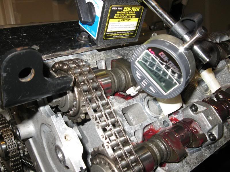 Since my LT5 is completely stock, I timed my cams according to Haibeck's recommendation which is 114 Deg ATDC for the intake cams and 110 Deg BTDC for the exhaust cams. He says this will give you a nice broad range of power and torque (3-7K RPM) which is a really good setting for drivability. This also happens to be the stock timing settings for the 405HP LT5's. The 375HP LT5's were timed to 114 Deg for both the intake and exhaust cams. I guess Lotus figured out that changing the exhaust cams to 110 BTDC setting gave better power. Although like Marc reports in his article, due to the lack of accuracy of the factory timing method, the timing of each cam can be off by as much as 4 degrees or so either way. So it is worth it to properly set the timing even on a stock LT5. With the dial indicator mounted to the driver's side intake cam (primary lobe, the one with a 'pointier' tip), I turned the crankshaft to put the cam in a position where cylinder #1 was not depressing the intake valves. I then zeroed the dial indicator. I used the original cam bolts during timing setting process so I wouldn't mess up the ARP cam bolts. Since they wouldn't be tightened fully, they would work fine for just snugging the bolt to check the timing. With the cam bolt snugged down, now I could check the timing of the driver's intake cam. Normal engine rotation is clockwise when facing the front cover of the engine and this is the direction you want to turn the crank when checking the timing. I used Marc's suggestion of .010" either side of max lift. So first I turned the crank clockwise until I found the max lift indicated on the dial indicator. Then I turned the crank until I reached .010" before max lift, recorded the degrees at the pointer on the timing wheel, turned the crank until .010" after max lift and recorded the degrees at the pointer again. So if the max lift was .389", you would go to .379" on either side of that max lift and record the degrees from the timing wheel on the crank. With the degree readings recorded, I just added them together and divided the result by 2. So if you got readings of 131 Deg and 95 Deg you would add those together to get 226. Divide that number by 2 and you get 113 Deg. This is the degrees that the center-line of the lobe on the cam you are checking is timed to in relation to the crankshaft. I found it is helpful to make marks with a fine-tipped Sharpie on the back of the cam sprocket where the cam meets it like in the picture below. That way when you have to readjust the cam, you can see where you started from and what degrees the cam was set to at that point. You can then start to get a feel for how much you have to turn the cam to get the setting you are aiming for. Which, it turns out is a very, very small amount once you are within several degrees of the setting you are aiming for. So I just continued re-adjusting and re-checking the cam until I got it to where I wanted it. 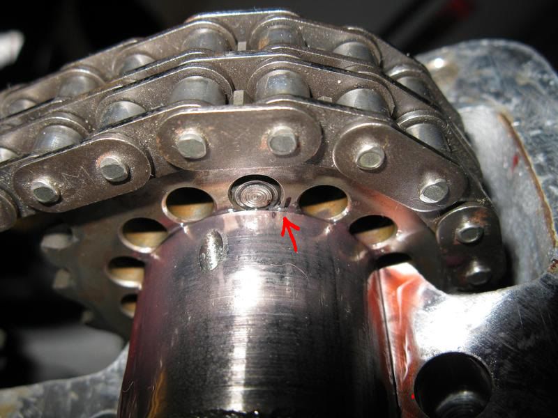 Once I got the driver's side intake cam set to the 114 Deg ATDC (actually I set the intake cams to 113 Deg ATDC & 111 Deg BTDC for the exhaust cams to account for continued timing chain wear as suggested by Marc in his timing article), I removed the old cam bolt, coated the washer with clean engine oil, put loctite 262 on the new ARP cam bolt and torqued it according to the factory procedure. For the final torquing, I found a way to hold the other end of the cam so that it would not move at all during the tightening procedure. This method also allows you to final tighten the cam bolts without having to have another person to help you. The pictures below show what I did. For the passenger side, I had to turn the engine sideways to use this method because the tightening direction is the opposite way on that side. 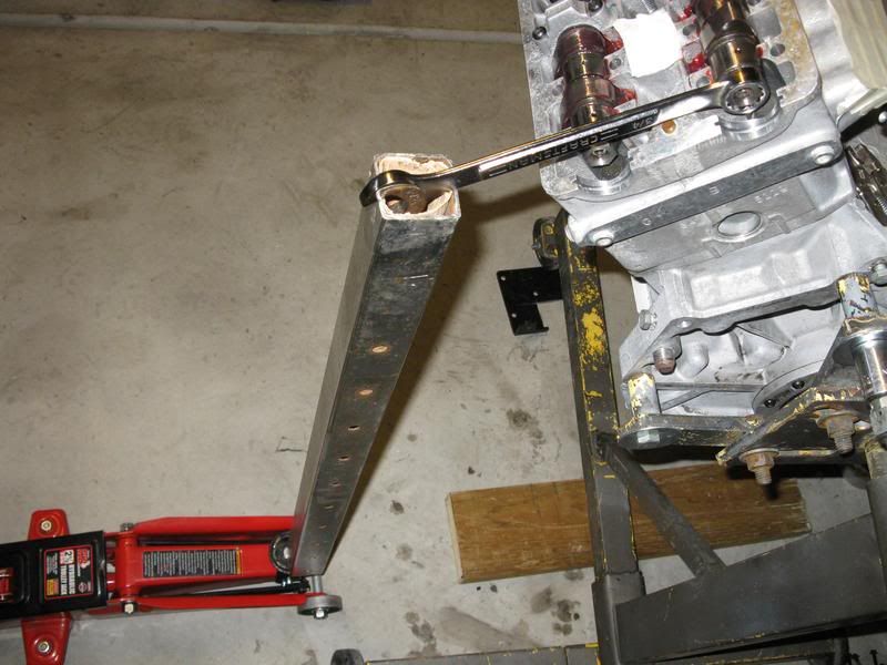 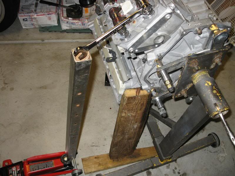
__________________
[IMG]http://i13.photobucket.com/albums/a292/bdw18_123/_zr1netforumsigphoto.jpg[/IMG][B] 1990 Corvette ZR-1 [/B][I] White/Flame Red, #2299, mostly stock, 144K miles.[/I] -Cams timed to the '93-'95 405HP LT5 stock timing. -IAT sensor relocated to below front bumper. -Haibeck hoops installed in airduct. -OBX cat-back exhaust. [COLOR=DarkRed][B](SOLD - December 2012 [/B][/COLOR][COLOR=DarkRed][B]:hello:)[/B][/COLOR] 1993 Corvette Coupe Black/Black, 6-speed (SOLD - October 2009 :hello:) Last edited by bdw18_123; 04-20-2011 at 03:18 PM. |

|

|
|
04-20-2011
|
#122 |
|
Join Date: Apr 2009
Location: Prather, CA
Posts: 809
|
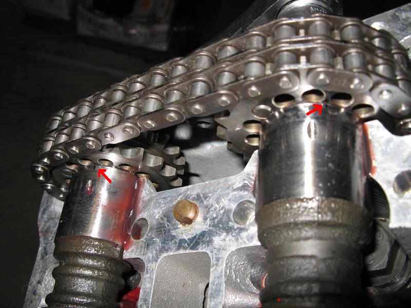
Just before I tightened the new cam bolts for the final time I made more marks as shown in the picture below (red arrows are pointing to the marks, they are a bit hard to see) on the back of the cam sprockets/cams so that I could tell if the cam moved at all after the final tightening was done.
 I then repeated that whole, long process I just described above for the other 3 camshafts. For the passenger side, I mounted the dial indicator to cylinder #6 as Marc describes in his timing article. Since this cylinder is one cycle behind cylinder #1, you can time the passenger cams off of it as if it was cylinder #1. Here are some pictures showing how I mounted the dial indicator to measure the driver's side and passenger's side exhaust cam. I forgot to take a picture of how I mounted the dial indicator to the passenger's side intake cam. 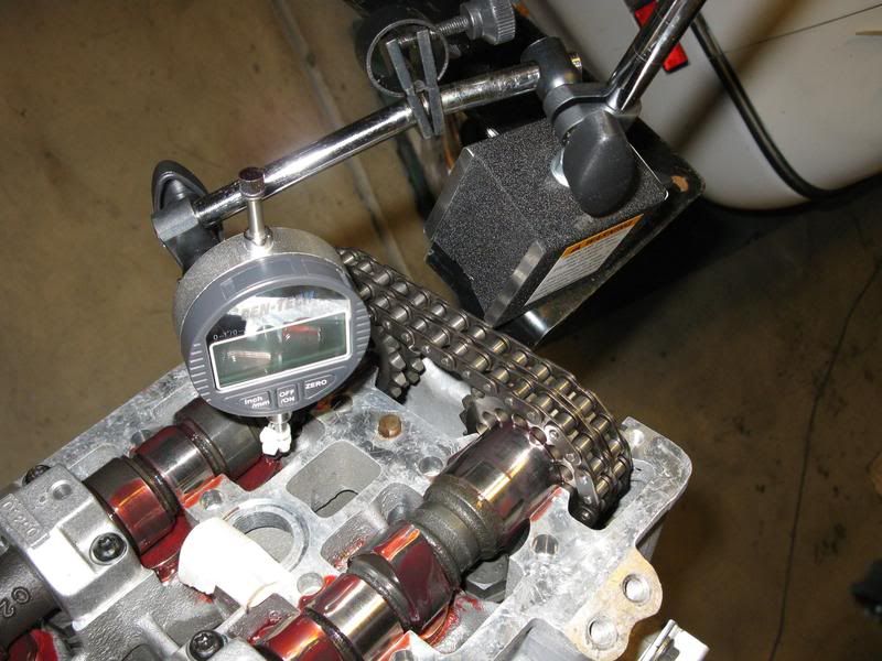 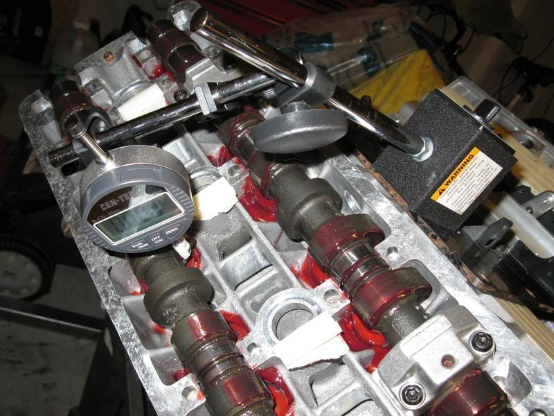 Driver's side cams timed and final torqued. 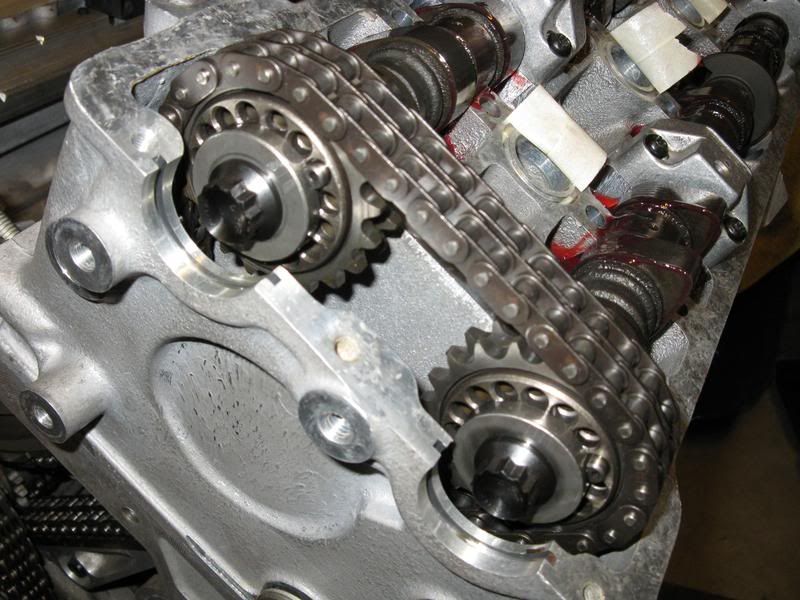 Passenger's side cams timed and final torqued. 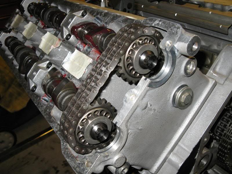 With that timing business finished and out of the way, I continued with assembling the rest of the engine. Next, I worked on getting the crankcase breather cover and baffle back in place. Baffle in place, loctite 262 applied and torqued down. 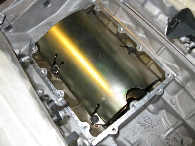
__________________
[IMG]http://i13.photobucket.com/albums/a292/bdw18_123/_zr1netforumsigphoto.jpg[/IMG][B] 1990 Corvette ZR-1 [/B][I] White/Flame Red, #2299, mostly stock, 144K miles.[/I] -Cams timed to the '93-'95 405HP LT5 stock timing. -IAT sensor relocated to below front bumper. -Haibeck hoops installed in airduct. -OBX cat-back exhaust. [COLOR=DarkRed][B](SOLD - December 2012 [/B][/COLOR][COLOR=DarkRed][B]:hello:)[/B][/COLOR] 1993 Corvette Coupe Black/Black, 6-speed (SOLD - October 2009 :hello:) |
|
|
|
|
04-20-2011
|
#123 |
|
Join Date: Apr 2009
Location: Prather, CA
Posts: 809
|
For the crankcase breather cover, for some reason, the service manual doesn't say to put any loctite on those bolts. But since the bolts in that cover have a reputation for becoming loose and making a big mess in the valley of the LT5, I decided to put some loctite 262 on them anyway to make sure they would stay tight. Since I had the heads already on, I had to temporarily remove the secondary linkage covers and the rods that link all the secondary plates together to get the cover to fit through to install it.
Cover installed with new gasket (from Jerry, of course) and torqued down. 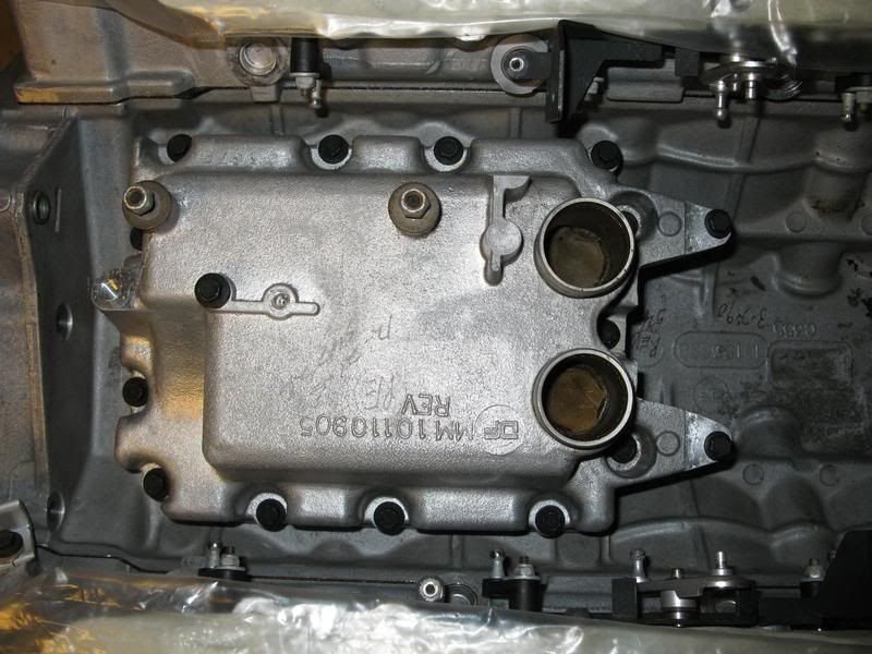 Starter went in next. I took the cover off of the back of the solenoid (the gold-colored one with the 3 small bolts) on the starter to check the contacts. They looked pretty good, but they need a little cleaning, so I cleaned them with some fine sandpaper and electro-contact cleaner and then put the cover back on. I then checked for proper operation by applying 12 volts to both the large bolt-terminal and the smaller connector to activate the starter. Starter installed and torqued down. 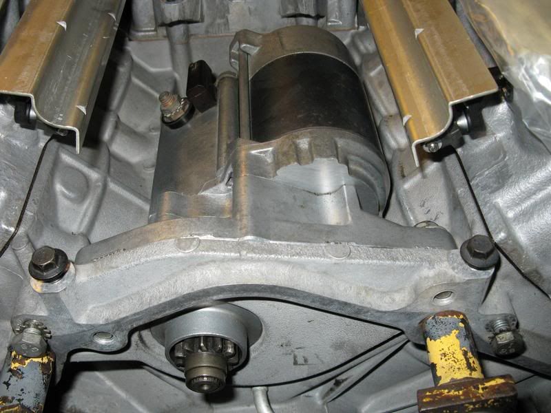
__________________
[IMG]http://i13.photobucket.com/albums/a292/bdw18_123/_zr1netforumsigphoto.jpg[/IMG][B] 1990 Corvette ZR-1 [/B][I] White/Flame Red, #2299, mostly stock, 144K miles.[/I] -Cams timed to the '93-'95 405HP LT5 stock timing. -IAT sensor relocated to below front bumper. -Haibeck hoops installed in airduct. -OBX cat-back exhaust. [COLOR=DarkRed][B](SOLD - December 2012 [/B][/COLOR][COLOR=DarkRed][B]:hello:)[/B][/COLOR] 1993 Corvette Coupe Black/Black, 6-speed (SOLD - October 2009 :hello:) |
|
|
|
|
05-20-2011
|
#124 |
|
Join Date: Apr 2009
Location: Prather, CA
Posts: 809
|
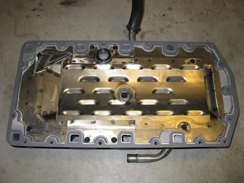
I decided to move on to the oil pan next.
First, I removed the baffle tray and the oil suction tube assembly. There was some nasty, sludgy stuff in the bottom of the pan. 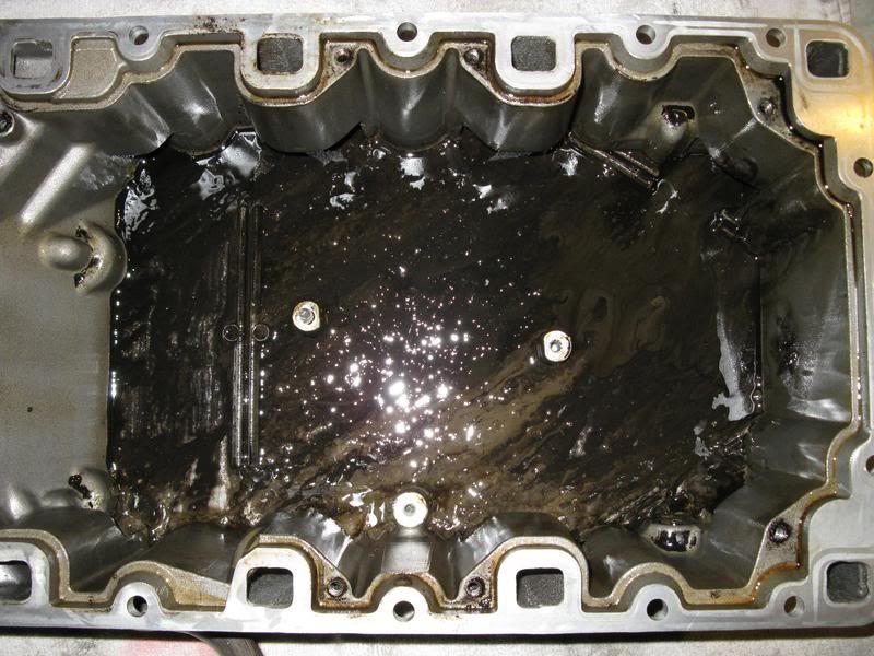 I also found some other "goodies" clustered underneath the oil suction tube. The screen on it prevented the pieces from being sucked up to the top of the engine. The "goodies" turned out to be more bits of broken chain rollers and a couple pieces of the plastic wear strip. I think the big plastic piece on the left in the picture may be the actual cause of the chain breaking. It looks like a piece of the cam cover wear strip that went between the chain and one of the sprockets (either the cam sprockets or the idler sprocket) when the engine was running. It may have even stayed on the sprocket it was on for several revolutions which would have put a lot of extra stress on the chain in that one spot, causing it to weaken and break. 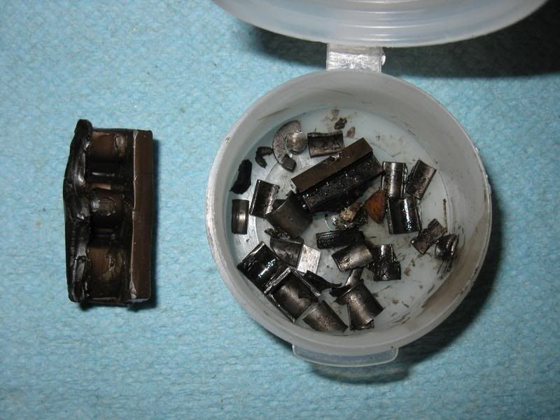 Oil pan, baffle tray and oil suction tube cleaned up and ready to be re-assembled. Note that the style of oil suction tube shown here is only on the '90-'92 375HP LT5's. The '93-'95 405HP LT5's have a different style of oil suction tube. Apparently the earlier cars don't have an oil level sensor on the oil pan either. That may have started with the 405HP LT5's but I'm not sure. Interestingly, that red, thin LT5 supplement service manual that says "90-93" (because technically, there are no '94 or '95 LT5's. Mercury Marine built the '94-'95 LT5's ahead of time in '93) only shows the later style of oil pick up tube. I had to go to my '90 service manual to find the assembly instructions for the earlier style. 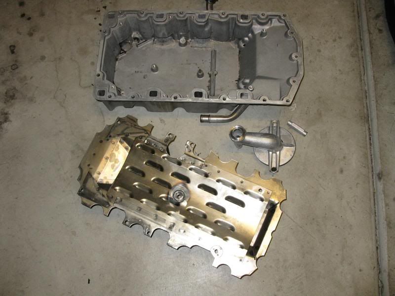 Oil suction tube re-attached to oil pan. 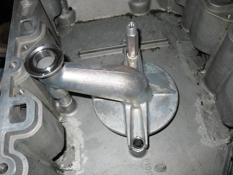 The o-ring for the top of the oil suction tube that you get from Jerry is thicker than the GM o-ring to provide a better seal, shown in the picture below. More info about this can be found at his website, linked below. http://jerrysgaskets.com/store2/root...products_id=29 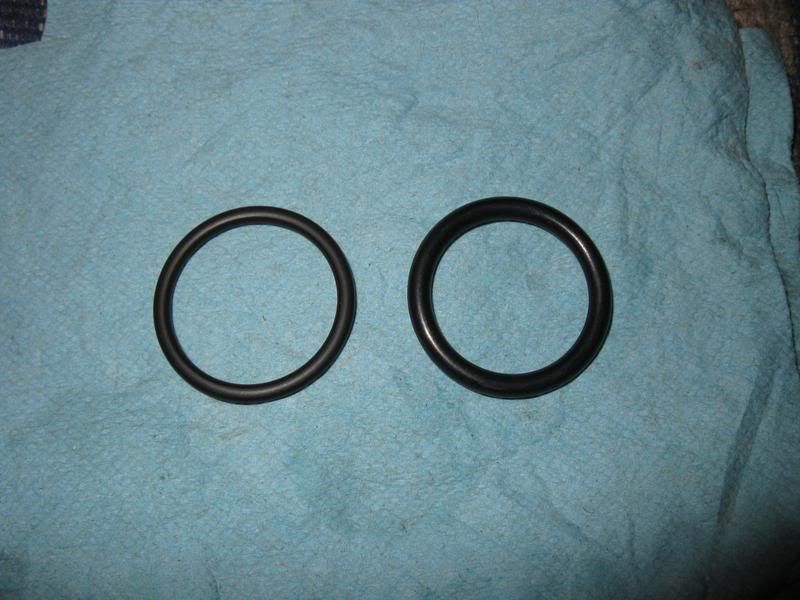 When installing the oil pan gasket, note that it can only go on one way. If you have it on upside-down, two of the holes will not line up, shown in the picture below. 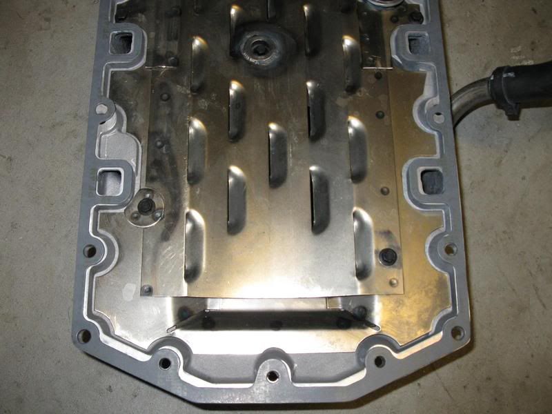
__________________
[IMG]http://i13.photobucket.com/albums/a292/bdw18_123/_zr1netforumsigphoto.jpg[/IMG][B] 1990 Corvette ZR-1 [/B][I] White/Flame Red, #2299, mostly stock, 144K miles.[/I] -Cams timed to the '93-'95 405HP LT5 stock timing. -IAT sensor relocated to below front bumper. -Haibeck hoops installed in airduct. -OBX cat-back exhaust. [COLOR=DarkRed][B](SOLD - December 2012 [/B][/COLOR][COLOR=DarkRed][B]:hello:)[/B][/COLOR] 1993 Corvette Coupe Black/Black, 6-speed (SOLD - October 2009 :hello:) |
|
|
|
|
05-20-2011
|
#125 |
|
Join Date: Apr 2009
Location: Prather, CA
Posts: 809
|
Baffle tray installed & oil pan gasket and suction tube o-ring in place.
 Oil pan installed. 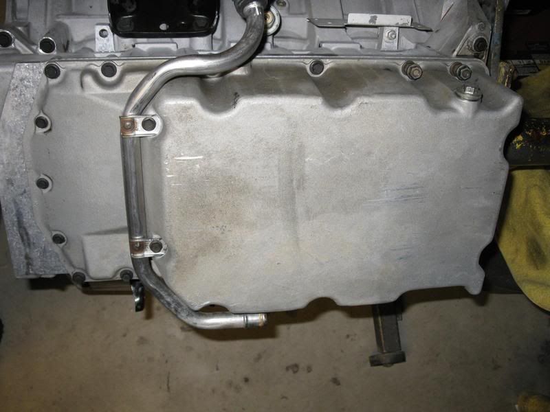 Secondary actuators went on next. I cleaned them up a bit with some Simple Green and and then a scotch brite pad. 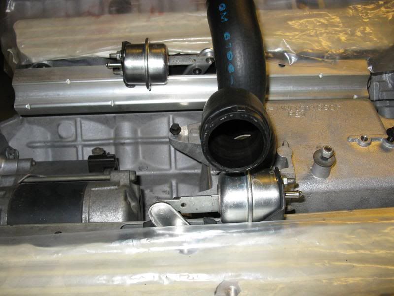 Apparently, there are a lot of ZR-1's out there with the secondary actuators installed upside-down (180 degrees out) from the factory. I found that mine were indeed in upside-down. I've heard this can cause the actuators to bind and possibly not open all the way. The picture below shows the correct orientation of the actuators. The bent over part of the metal arm that is attached to the rubber should be pointing to the center of the engine. Now, I did test my actuators several times with a hand-operated vacuum pump with the actuators upside-down and they seemed to open fine with out binding, so maybe the upside-down actuator thing isn't as big a deal after all. Because if so many Z's were not making full power because of the secondaries not opening all the way, I would think that issue would have been caught a long time ago. But I installed mine in the correct orientation anyway. 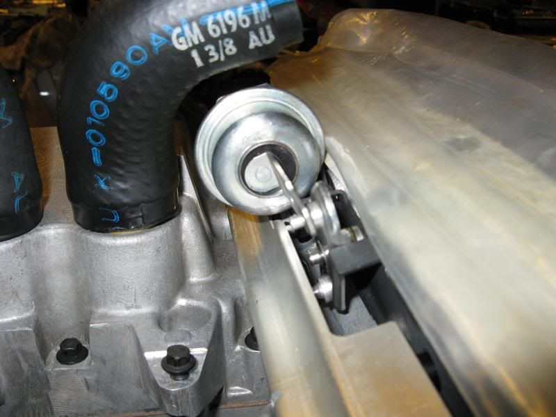 Time to install the timing chain tensioners next. The instructions I followed for resetting mine are at the following link (also linked in Dynomite's "Solutions" thread sticky): http://www.zr1.net/forum/showthread.php?t=14693 Tensioners cleaned up, reset and ready to be reinstalled. 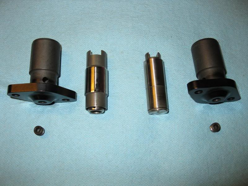 Driver's side tensioner installed. 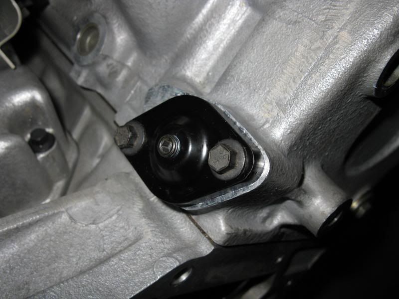
__________________
[IMG]http://i13.photobucket.com/albums/a292/bdw18_123/_zr1netforumsigphoto.jpg[/IMG][B] 1990 Corvette ZR-1 [/B][I] White/Flame Red, #2299, mostly stock, 144K miles.[/I] -Cams timed to the '93-'95 405HP LT5 stock timing. -IAT sensor relocated to below front bumper. -Haibeck hoops installed in airduct. -OBX cat-back exhaust. [COLOR=DarkRed][B](SOLD - December 2012 [/B][/COLOR][COLOR=DarkRed][B]:hello:)[/B][/COLOR] 1993 Corvette Coupe Black/Black, 6-speed (SOLD - October 2009 :hello:) |
|
|
|
|
05-20-2011
|
#126 |
|
Join Date: Apr 2009
Location: Prather, CA
Posts: 809
|
Passenger side tensioner installed.
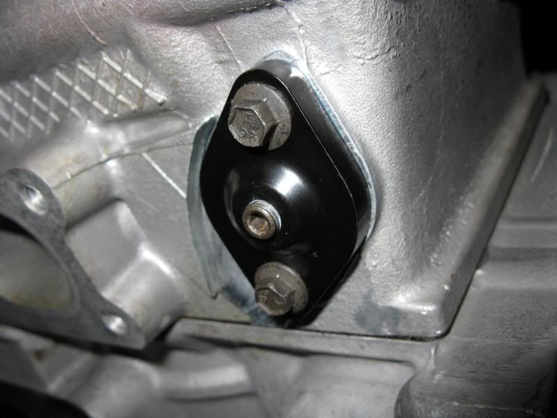 Before putting the front cover on, I put the red assembly grease I've been using on all the chains and sprockets so they won't be dry for the initial start-up. Front cover and water pump installed. Yes, I know there is a bolt missing from the water pump in the picture. I'm missing one of the T-40 bolts and all four of the bolts for the water pump pulley. They are on the way from Jerry. 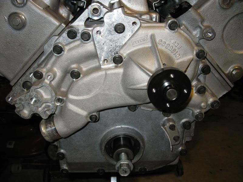 That's it for this update!
__________________
[IMG]http://i13.photobucket.com/albums/a292/bdw18_123/_zr1netforumsigphoto.jpg[/IMG][B] 1990 Corvette ZR-1 [/B][I] White/Flame Red, #2299, mostly stock, 144K miles.[/I] -Cams timed to the '93-'95 405HP LT5 stock timing. -IAT sensor relocated to below front bumper. -Haibeck hoops installed in airduct. -OBX cat-back exhaust. [COLOR=DarkRed][B](SOLD - December 2012 [/B][/COLOR][COLOR=DarkRed][B]:hello:)[/B][/COLOR] 1993 Corvette Coupe Black/Black, 6-speed (SOLD - October 2009 :hello:) |
|
|
|
|
05-20-2011
|
#127 |
|
Join Date: Mar 2009
Location: Orlando, FL
Posts: 1,828
|
Great pics, great progress!
BTW, the oil level sensor issue -- just as a data point, my early 1991 (#302) has one. Not sure when that started.
__________________
2004 Z06/Z16 LeMans Commemorative Edition 1991 ZR-1 #302 White/Gray (sold) 1991 ZR-1 #1147 Red/Saddle (sold) |
|
|
|
|
05-20-2011
|
#128 |
 Join Date: Dec 2003
Location: Arcadia,OK
Posts: 3,376
|
Ben,
Very good photographs and excellent narrative. Thanks for sharing your project with us!
__________________
Jerry Downey JERRYS LT5 GASKETS & PARTS http://www.jerrysgaskets.com 1994 ZR-1, Black/Black, Lingenfelter Aerobody, 416cu in, 3.91 gears, coil-over susp, Brembo brakes, etc. 2016 Black-Red, 3LT-Z51 Auto 8-speed. |
|
|
|
|
05-20-2011
|
#129 | |
|
Join Date: Apr 2009
Location: Prather, CA
Posts: 809
|
Quote:
__________________
[IMG]http://i13.photobucket.com/albums/a292/bdw18_123/_zr1netforumsigphoto.jpg[/IMG][B] 1990 Corvette ZR-1 [/B][I] White/Flame Red, #2299, mostly stock, 144K miles.[/I] -Cams timed to the '93-'95 405HP LT5 stock timing. -IAT sensor relocated to below front bumper. -Haibeck hoops installed in airduct. -OBX cat-back exhaust. [COLOR=DarkRed][B](SOLD - December 2012 [/B][/COLOR][COLOR=DarkRed][B]:hello:)[/B][/COLOR] 1993 Corvette Coupe Black/Black, 6-speed (SOLD - October 2009 :hello:) |
|
|
|
|
|
08-28-2011
|
#130 |
|
Join Date: Apr 2009
Location: Prather, CA
Posts: 809
|
It's been awhile since my last update. I have been working on my Z, but I just haven't had the time to post detailed updates as often as I used to.
I'm getting very close to being able to try firing this beast up (possibly today, we will have to see how things go). But let's continue where my last update left off... With the front end back together, I then got the cam position sensor installed. I painted the bracket and put new convo-tubing (the good kind with the gray stripe) on the wiring harness. 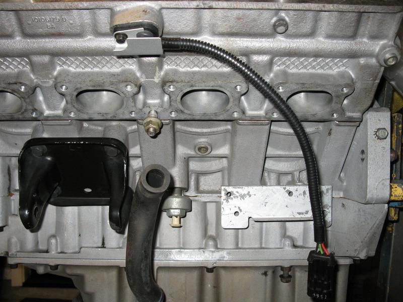 It was then time to move on to getting the top end components ready for painting. I had looked into getting the damaged driver's cam cover and coolant tube welded, but the guy I talked to said they couldn't be welded because they were cast pieces. Well, I didn't want to spend more time looking for someone who could weld them or sending them somewhere, so I just decided to go ahead and repair them with JB-Weld. I have repaired many things with this stuff and it always works well. It is temp rated to 600 degrees and is really tough stuff; I know it isn't ideal, but I think it will work just fine. Pics of the repairs. First though, a pic of the damaged coolant tube before, it is kind of fuzzy, but it is the only picture I have of that coolant tube before. 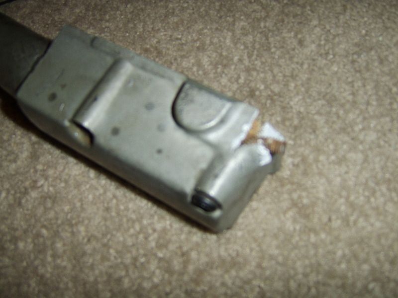 I had to re-form the missing chunk of the coolant tube after the JB-Weld dried; I used the other coolant tube to go by to re-form that part, turned out pretty good. 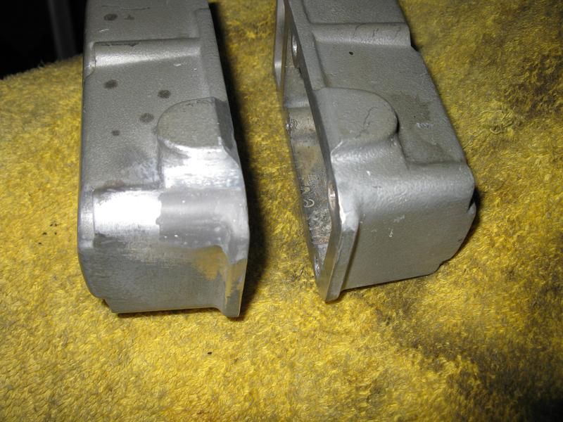 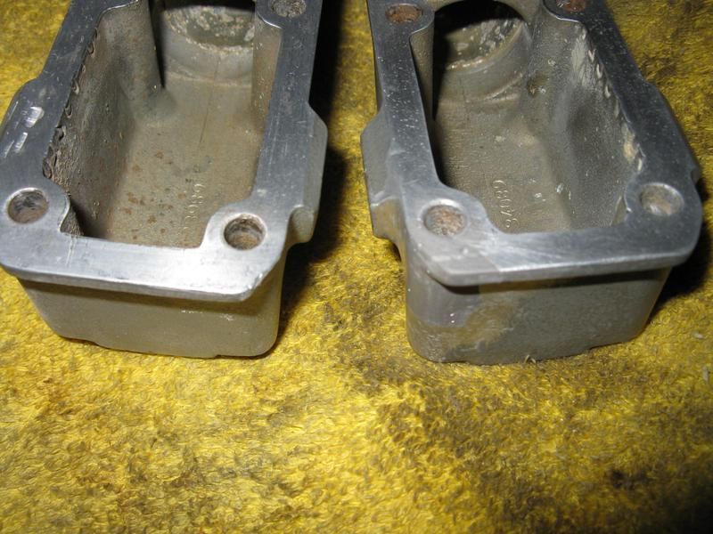 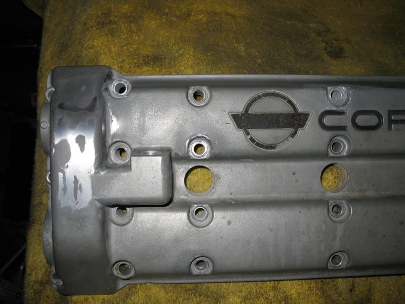 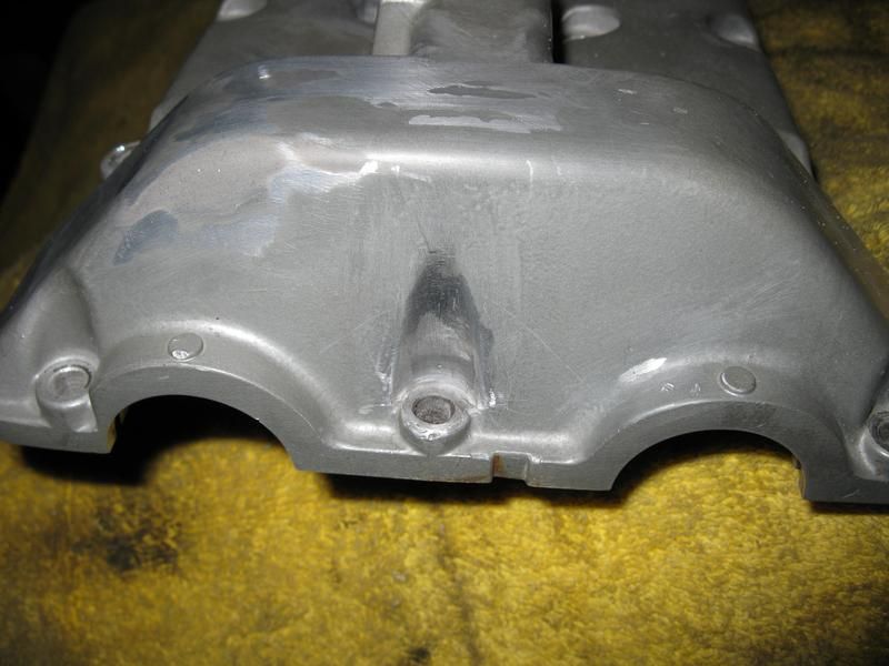
__________________
[IMG]http://i13.photobucket.com/albums/a292/bdw18_123/_zr1netforumsigphoto.jpg[/IMG][B] 1990 Corvette ZR-1 [/B][I] White/Flame Red, #2299, mostly stock, 144K miles.[/I] -Cams timed to the '93-'95 405HP LT5 stock timing. -IAT sensor relocated to below front bumper. -Haibeck hoops installed in airduct. -OBX cat-back exhaust. [COLOR=DarkRed][B](SOLD - December 2012 [/B][/COLOR][COLOR=DarkRed][B]:hello:)[/B][/COLOR] 1993 Corvette Coupe Black/Black, 6-speed (SOLD - October 2009 :hello:) |
|
|
|
 |
|
|


 Linear Mode

